

Description
Howard
DGA-5 "IKE”
a "DamnedGood Airplane”
Version 3.1
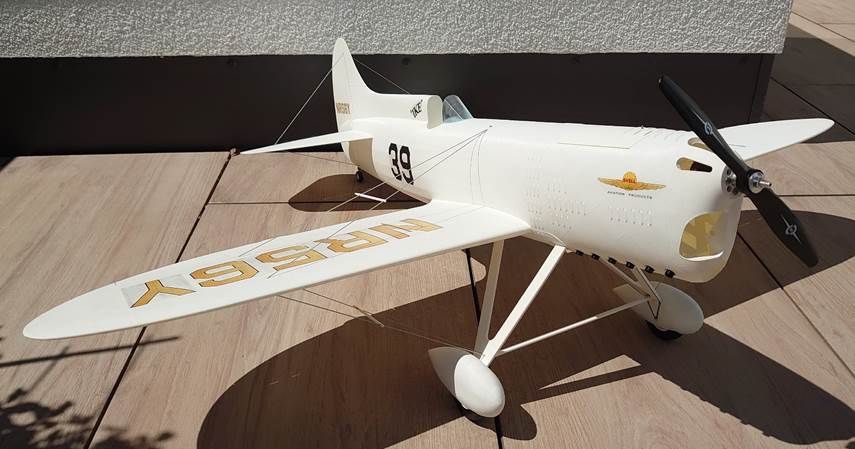
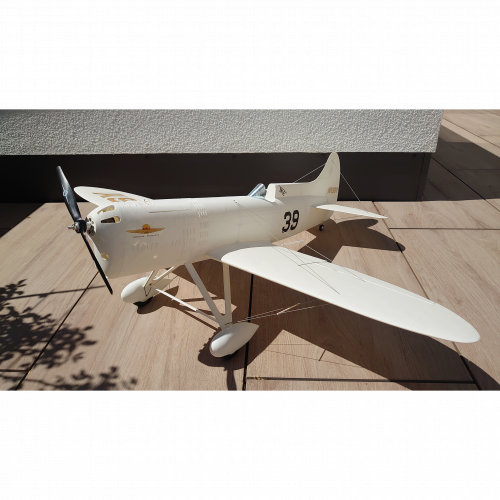
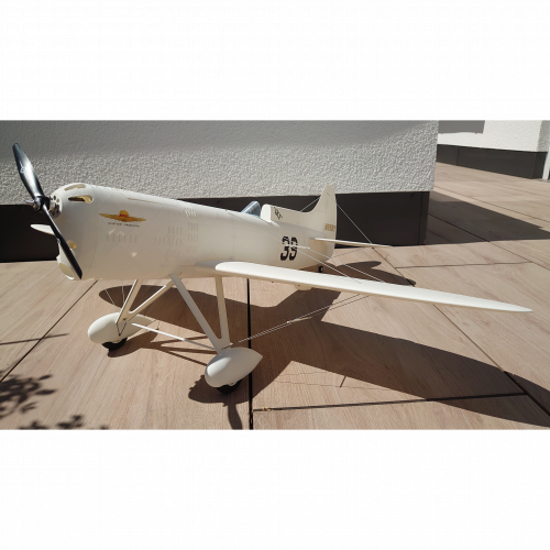
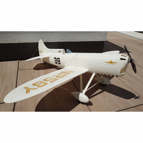
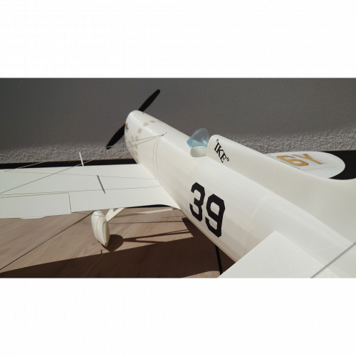
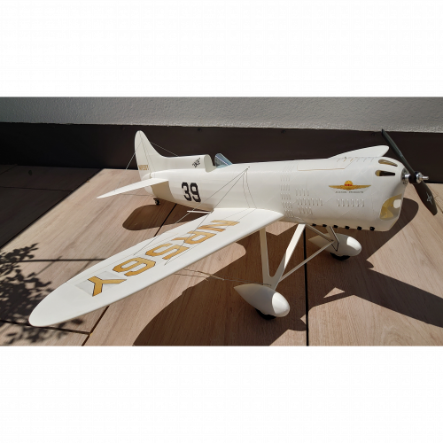
Figure 1: 3D-printed Howard DGA-5 "IKE” using pre-foamed PLA.
|
Scale: Length: Wingspan: Wing airfoil: Tail airfoil: Empty weight [LWPLA/PLA+]: Takeoff weight [LWPLA/PLA+]: Wing area: Wing load [LWPLA/PLA+]: Channels: |
1 : 6.1 850 mm 1000 mm NACA0012 à NACA0009 NACA0003 [530/650] g [880/1000] g 16 dm2 [55/62.5] g/dm2 5 |
Content
Noteworthy changes in assembly for version 3
The original
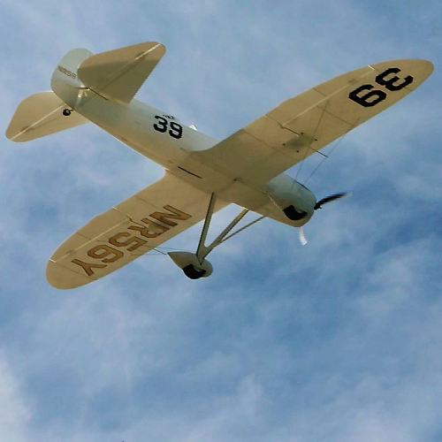
The Howard DGA-5 "IKE” evolved from one of two almost identical prize-winning racers "MIKE” and "IKE”developed by Benny Howard in 1932 [1]. From 1932 to 1936 both planes won plenty of racing prices culminating in 1935 when Howard aircraft won the Bendix, Thomson, and Greve Trophy – a season of racing events that became unofficially known as "Benny Howard National Air Races” [2].
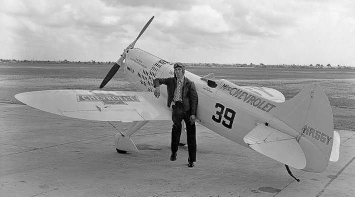
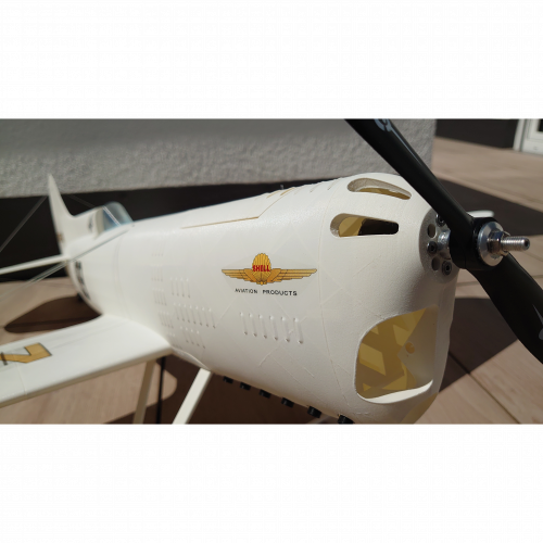
Figure 2: Harold Neumann with Miss Chevrolet in Miami, Florida. "Ike” (NR56Y) was sponsored by the Chevrolet Division of General Motors and was therefore also known as "Miss Chevrolet” [3].
What you get
This is a thoroughly designed 3D printable scale version of the original Howard DGA-5 "IKE”. I spent considerable amount of time with prototype testing and continuous refinement to improve printability, surface quality, scale characteristics, flight characteristics, and rigidity.
This aircraft can be built
· with or without landing gear
· with or without flying wires
· completely in PLA+ or partly in LW-PLA
3D print files
The package includes a complete set of STL files, a set of PrusaSlicerproject files, and the hereof generated gcode. PrusaSlicer is a powerful open-source software that can be used for free. The project files were created with version 2.7.1 and contain all detailed print settings required to optimally print each airplane part.
Note: If you want to use different slicer software, please make sure to check and reapply all part-dependent print settings provided in the PrusaSlicer project files. Otherwise, some parts may not print as desired.
|
STL |
STL stands for Standard Tessellation Language, a file format that
describes the surface geometry of a three-dimensional object. Moreover, for some parts modified STL files are provided for optional printing with active foaming Low-Weight-PLA. |
|
Project files |
Multiple STL files can be combined into a single project file
(3mf) and "print job” (gcode). Specific slicer settings can be applied to
e.g., increase the stability of a certain part area or improve the
printability of an area with a large overhang angle. |
|
Gcode |
For each project file and each active foaming LW-PLA printable part corresponding gcode files are provided to minimize your preparation time. Please note that these gcode files were generated for the Prusa i3 MK3S. For many 3D printers and filaments, the gcode should just work fine. If you experience issues with the print quality, I recommend having a closer look at the slicer parameters to optimize the gcode for your printer. |
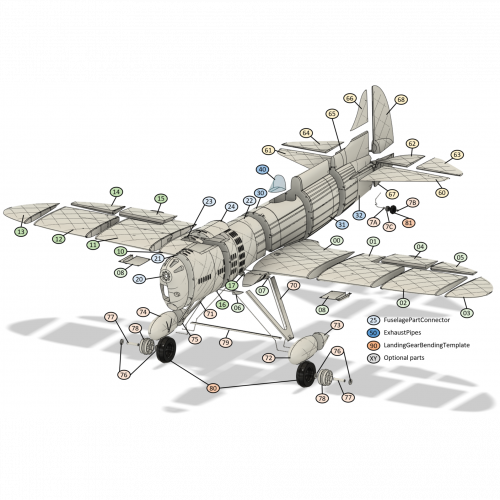
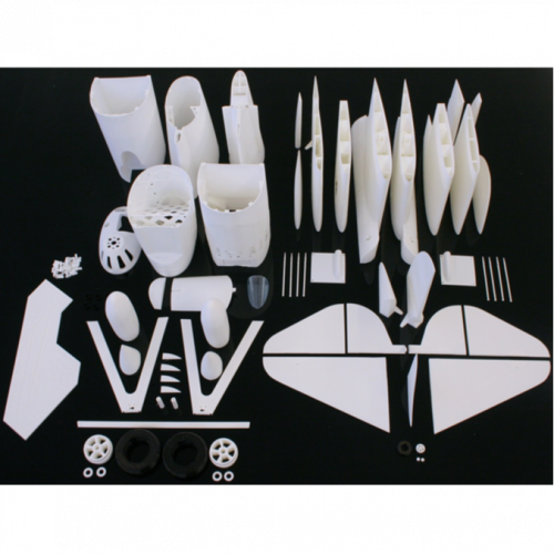
Figure 3 depicts an exploded view of the Howard DGA-5 "IKE”. Together with the following part list it provides an overview of all 3D printable parts. The color code of the index numbers visualizes to which project file and gcode the part belongs.
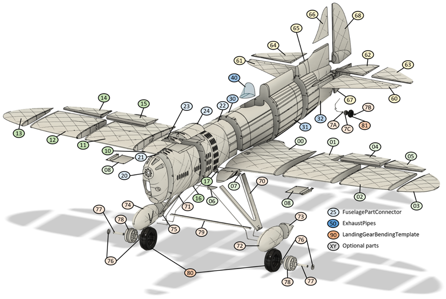
Figure 3: Exploded view with labeled plane parts.
|
Project (.3mf/.gcode) |
Part name (.stl) |
Idx |
Print weight |
|
|
WingLeft
time: 19h 1m |
Wing1L Wing2L Wing3L Wing4L Aileron1L Aileron2L LandingGearShimFrontL LandingGearShimBackL ServoCover (left+right) |
00 01 02 03 04 05 06 07 08 |
Pre-foamed 46 g 27 g 22 g 10 g 8 g 4 g < 1 g < 1 g 4 g |
PLA+ (default) 57 g 34 g 27 g 12 g 10 g 5 g < 1 g < 1 g 5 g |
|
WingRight
time: 18h 50min |
Wing1R Wing2R Wing3R Wing4R Aileron1R Aileron2R LandingGearShimFrontR LandingGearShimBackR SpacerFlyingWires |
10 11 12 13 14 15 16 17 18 |
Pre-foamed 46 g 27 g 22 g 10 g 8 g 4 g < 1 g < 1 g < 1 g |
PLA+ (default) 57 g 34 g 27 g 12 g 10 g 5 g < 1 g < 1 g 1 g |
|
FuselagePart1
time: 14h 6m |
Fuselage1 Fuselage2 Fuselage3 CanopyFront CanopyBack FuselagePartConnector (45pcs) |
20 21 22 23 24 25 |
Pre-foamed 20 g 30 g 30 g 5 g 2 g < 1 g |
PLA+ (default) 25 g 38 g 39 g 6 g 2 g 1 g |
|
FuselagePart2
time: 10h 14m |
Fuselage4 Fuselage5 Fuselage6 |
31 32 32 |
Pre-foamed 28 g 22 g 25 g |
PLA+ (default) 35 g 28 g 31 g |
|
WindShield
time: 0h 18m |
WindShield |
40 |
|
PLA (default) 1 g |
|
ExhaustPipes
time: 0h 6m |
ExhaustPipe (6pcs) |
50 |
|
PLA (default) < 1 g |
|
Tail
time: 9h 59m |
HorizontalStabilizerL HorizontalStabilizerR ElevatorL1 ElevatorL2 ElevatorR1 ElevatorR2 VerticalStabilizer RudderBottom RudderTop |
60 61 62 63 64 65 66 67 68 |
Pre-foamed 12 g 12 g 5 g 6 g 5 g 6 g 2 g 4 g 10 g |
PLA+ (default) 15 g 15 g 6 g 7 g 6 g 7 g 3 g 6 g 13 g |
|
LandingGearParts
time: 6h 24m |
LegL LegR WheelPantFrontL WheelPantBackL WheelPantFrontR WheelPantBackR WasherMainWheel (4pcs) AxleMainWheel (2pcs) RimMainWheel (2pcs) Crossbar WasherTailWheelL WasherTailWheelR RimTailWheel
|
70 71 72 73 74 75 76 77 78 79 7A 7B 7C |
Pre-foamed 6 g 6 g 7 g 2 g 7 g 2 g < 1 g < 1 g 6 g < 1 g < 1 g < 1 g < 1 g |
PLA+ (default) 8 g 8 g 9 g 2 g 9 g 2 g < 1 g < 1 g 8 g < 1 g < 1 g < 1 g < 1 g |
|
Tires
time: 1h 49m |
TireMainWheel (2pcs) TireTailWheel |
80 81 |
TPU 18 g 1 g |
|
|
LandingGearBending
time: 2h 8m |
LandingGearBendingTemplate |
90 |
|
PLA (default) 24 g |
|
Optional: ServoHolderDS843MG
time: 1h 12m |
ServoHolderDS843MG (4pcs) |
A0 |
Pre-foamed 9 g |
PLA+ (default) 11 g |
|
Optional: ServoHolderDS939MG
time: 1h 16m |
ServoHolderDS939MG (4pcs) |
B0 |
Pre-foamed 9 g |
PLA+ (default) 11 g |
|
Alternative: WingL1FrontBack
time: 7h 37m |
WingL1Front WingL1Back |
010 011 |
Pre-foamed 4 g 43 g |
PLA+ (default) 5 g 54 g |
|
Alternative: WingR1FrontBack
time: 7h 37m |
WingR1Front WingR1Back |
100 101 |
Pre-foamed 4 g 43 g |
PLA+ (default) 5 g 54 g |
|
Alternative: Tail LW-PLA
Print each active foaming LW-PLA part separately! |
HorizontalStabilizerL HorizontalStabilizerR ElevatorL1 ElevatorL2 ElevatorR1 ElevatorR2 RudderBottom RudderTop |
600 610 620 630 640 650 670 680 |
Active foaming 8 g 8 g 4 g 4 g 4 g 4 g 4 g 7 g |
|
|
Alternative: Ailerons & Servo Cover
Print each active foaming LW-PLA part separately! |
Aileron1L Aileron2L Aileron1R Aileron2R ServoCover (left + right) |
040 050 140 150 080 |
Active foaming 5 g 3 g 5 g 3 g 2 g |
|
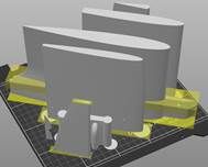
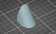
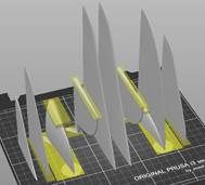
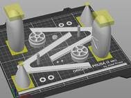
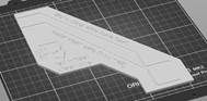
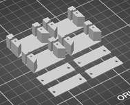
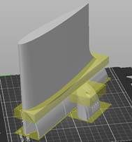
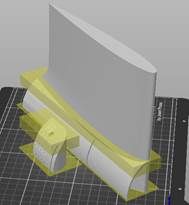
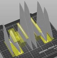
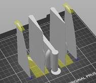
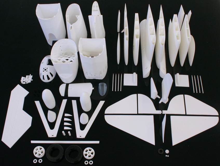
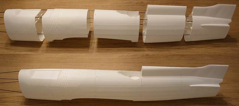
Figure 4: All printed parts at a glance.
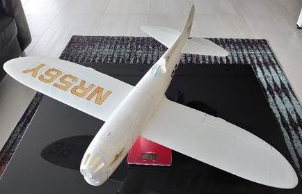
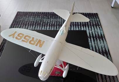
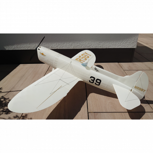
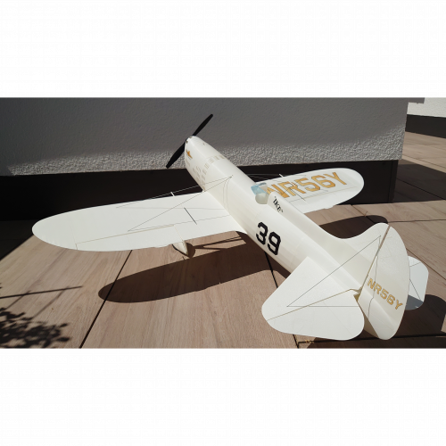
Figure 5: Assembled plane printed with
pre-foamed PLA.
Left: 478g without landing gear and flying wires. Right: 554g with landing gear
and flying wires.
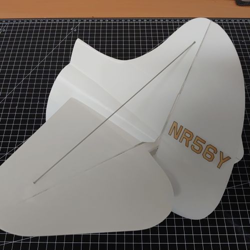
Decal sheets
The set includes PDF files (600dpi, letter and A4 format) to print decals for the Howard DGA-5 "IKE”. The original plane used black aircraft registration letters in the first years which were later partly replaced by golden letters. Unfortunately, gold is a special color that can only be approximated by the RGB or CMYK color space. Therefore, black registration letters are provided as an alternative.

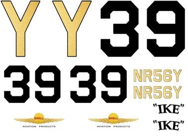
Figure 5: Decal sheets with golden registration letters.

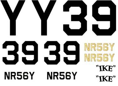
Figure 6: Decal sheets with black registration letters.
What you need
3D printer specification
All STL files have been successfully tested with my Prusa i3 MK3S.
|
3D print volume
|
Minimum requirement for single STL file (ensures printability of
all plane parts): Optional files (STL, project, gcode) are provided to print the most inner wing parts with such small printer bed sizes (see optional print parts below). Minimum requirement for other gcode: X ≥ 240mm; Y ≥ 200mm; Z ≥ 171mm |
|
Nozzle diameter |
0.4mm |
|
Filament support |
PLA, TPU |
Required materials
Most plane parts are printable except for a few components such as steel wires or nylon screws. For the parts printed with white PLA I recommend using either PLA+ (Premium PLA) or pre-foamed PLA.
Overture PLA Professional (PLA+) is my first insider tip. It has a much higher tensile strength compared to standard PLA and a higher glass transition temperature. Structural details and surface finish are excellent.
Overture Air PLA (pre-foamed PLA) is my second insider tip. Compared to PLA+ it weighs approximately 20% less. This pre-foamed PLA can be printed with almost the same slicer settings as used for standard PLA. Thanks to lower nozzle temperatures, stringing can be handled much better compared to active foaming LW-PLA. Printing multiple parts at the same time is possible. Also, the stiffness of the printed parts is notably better compared to LW-PLA. The following filament print setting modifications are typically sufficient to successfully print Overture Air:
· Nozzle temperature: ~205°C (high enough for good layer adhesion, low enough to minimize stringing)
· Retraction length (direct extruder): ~3mm (effectively reduces stringing)
· Retraction speed (direct extruder): ~30mm/s (lower is better to avoid negative side effects)
· Deretraction extra length: 0.08mm (to improve z seam)
Let me emphasize that the recommendation above is based on my personal experience. I do not get anything from Overture.
|
Filament |
White PLA for majority of print parts: ~665g for PLA (e.g., Overture PLA Professional White) or ~530g for pre-foamed PLA (e.g., Overture Air PLA White) Black PLA for exhaust pipes: ~2g (or paint white PLA printout with black color) Transparent PLA for the wind shield: ~2g (e.g., Fillamentum PLA Crystal Clear Iceland Blue) Black TPU for tires: ~15g, (e.g., 3DFILS eFil TPU 90A) Optionally, white active-foaming LW-PLA for horizontal stabilizers, rudders, ailerons, and wing servo covers: ~61g (e.g., colorFabb LW-PLA NATURAL) |
|
Spring steel wires
|
Ø 1.0mm, 2pcs of length ~800mm (servo linkage rods) Ø 1.0mm, 1pc of length ~70mm (tail landing gear) Ø 1.5mm, 1pc of length ~930mm (main landing gear) |
|
Linkage stopper |
2pcs for servo linkage rods e.g., Hobbyking Brass Linkage Stopper For 1mm Pushrods |
|
Screw-in nuts |
2pcs M4x10 (outer Ø ≤8.0mm, sometimes used for furniture) |
|
Self-tapping screws |
8pcs M2.3x6 for wing servo cover 8pcs M2.3x6 for servo holder (optional) |
|
Nylon screws |
2pcs M4x20mm |
|
CA hinge sheet |
|
|
Elastic cord |
Ø 1.0mm, grey or white (flying wires, I use grey color) |
|
Carbon fiber rod |
Optional: Ø 2.0mm, 1pc of length 250mm. Generally recommended if LW-PLA (pre-foamed or active foaming) is used for the horizontal stabilizers. Optional: Ø 1.5mm, 4pcs 900mm. Generally recommended if pre-foamed LW-PLA is used for the fuselage. |
|
Carbon fiber pipe |
Optional: Outer Ø 6.0mm, inner Ø 4.0mm, 1pc of length 700mm. Intended as reinforcement of the wing to support cunning aerobatic figures. |
|
CA glue |
Medium viscosity e.g., Hobbyking Super Glue CA (50g / 1.7oz) Medium |
|
CA accelerator |
Optional: E.g., Hobbyking Insta-Set CA Accelerator 2. Oz |
|
Double-sided tape |
Strong sticky tape to fix the receiver (and optionally the servos) to the airplane e.g., Hobbyking Double Sided Tape (Clear) 25mm x 1m |
|
Decal sheet |
2pcs A4 or letter format (e.g., inkjet waterslide decal paper) |
|
Clear spray coating |
~200ml, for decal sheets (e.g., acrylic clear finish) |
Radio control components
There is a large variety of products available which fulfill the requirements to provide enough power and precise control for the Howard DGA-5 "IKE”. The following set is what I am currently using and can recommend. It provides a maximum thrust to weight ratio of 1.2 to 1.4 (according to ecalc.ch) and a mixed flight time of more than 7 minutes.
|
Motor |
Hobbyking PROPDRIVE v2 2836 1200KV (max. Ø 32mm) |
|
ESC |
Hobbyking Turnigy Plush-32 30A (2~4S) Brushless Speed Controller W/BEC |
|
Battery |
|
|
Propeller |
|
|
Servos (4pc) |
|
|
RC control |
5 channel TX/RX |
Assembly
Step by step video guide
This video guide is based on version 1 of this 3D printable Howard DGA-5 "IKE”. Some parts of version 3 look slightly different. Relevant changes are explained in the following subchapters.
Howard DGA-5 "IKE” – step by step video guide
Chapters:
00:15 > Right wing
04:02 > Left wing
05:18 > Combine wings
06:49 > Servo cover
07:43 > Fuselage
16:59 > Tail
24:04 > Landing gear
31:24 > Decals
33:56 > Radio control
39:06 > Flying wires
41:26 > Final check
Noteworthy change in version 3.1
Added tubes to optionally stabilize the fuselage with Ø 1.5mm carbon rods.
Noteworthy changes in assembly for version 3
Partly applied selective brim instead of continuous brim to reduce the post-processing effort of the printed parts before assembly. The connection of the wing parts has changed to avoid additional post-processing steps in case of an elephant foot of the printed components. The landing gear crossbar is printed as one part.
Since version 2.1 there is the option to insert a carbon fiber pipe into the center area of the wing. Doing so further increases the stability of the wing and ensures sufficient endurability for all cunning aerobatic figures. Please make sure to check if the pipe fits into the prepared hole in the wing parts before gluing them together. Insert the carbon pipe before you glue both wing halves together.
Since version 2 the rudders, stabilizers, ailerons, and wing servo covers of the airplane are optionally available for printing with active foaming LW-PLA. The design of these parts has been modified to minimize extra travel moves of the nozzle during the print process and to partly compensate for the reduced stiffness of the foamed PLA. At one side of the print (bottom side except for the rudder) the rib structure becomes more visible along the surface. As shown in Figure 7, this visual effect can be easily minimized by sanding the area of the rib structure.
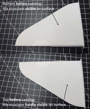
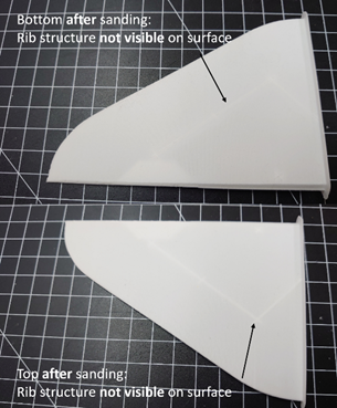
Figure 7: ElevatorL2 before (left) and after (right) sanding.
The active foaming LW-PLA horizontal stabilizers and fuselage part 6 have tubes to optionally insert a 2mm carbon fiber rod to improve rigidity and simplify the assembly as can be seen in Figure 8.
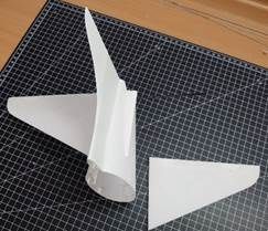
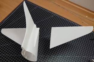
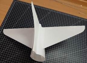
Figure 8: Optional 2mm carbon fiber rod
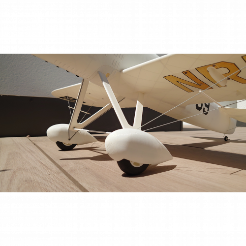
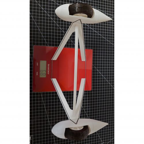
The main landing gear has been weight-optimized
with version 2. This is mainly realized by reducing the diameter of the spring
steel wires from 2.0mm to 1.5mm. To ensure robustness, the crossbar became
slightly thicker. Overall weight reduction is approx. 13g resulting in a total
weight of 68g.
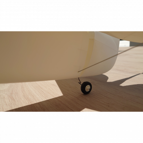
Also the tail wheel became more light weight by reducing the diameter of the
spring steel wire from 1.5mm to 1.0mm and optimizing the weight of rim and
tire. Despite these optimizations the landing gear remains robust.
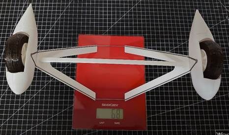
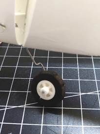
Figure 9: Weight-optimized landing gear and tail wheel
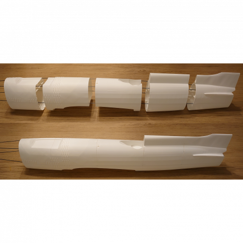
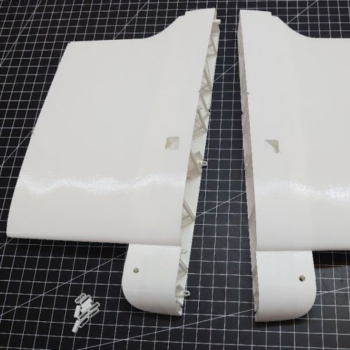
Since version 2 connectors can be used to
simplify the step of aligning and gluing both wing halves together. The
assembly process is comparable to the fuselage parts. Figure 10 (left) depicts
WingL1 and WingR1 with connectors inserted in WingR1. Please note that this
change only applies to the central wing parts.
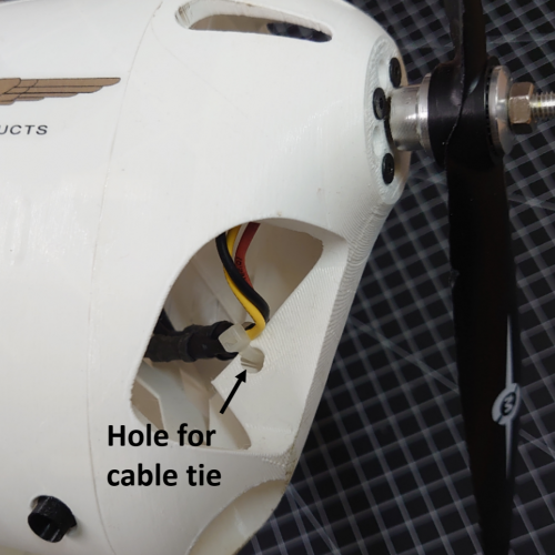
Fuselage1 now offers the possibility to fix the motor cables with a cable tie
as shown in Figure 10 (right).
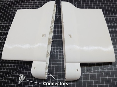
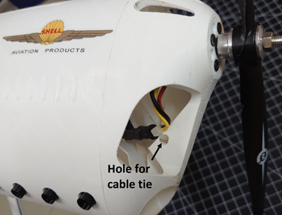
Figure 10: Connectors are available to simplify the alignment of left- and right-wing halves (left). Motor cables can be fixed to the fuselage (right).
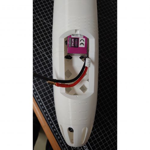
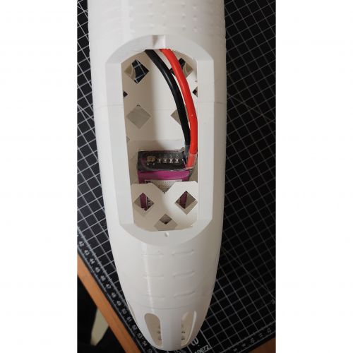
Another useful modification is the extension of the battery compartment. Version 2 provides more degrees of freedom in the choice of battery type and size which is especially useful in combination with active foaming LW-PLA printed tail parts to adjust the center of gravity. Also, the required manual cut-out has been simplified.
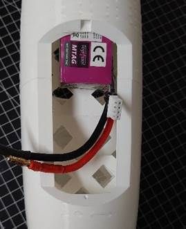
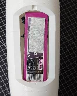
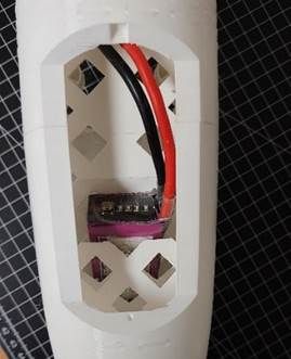
Figure 11: Extended battery compartment to adjust center of gravity.
In version 3, the size of the battery compartment has been increased to support additional batteries. Maximum supported dimensions are 140mm x 38mm x 28.5mm.
Pre-flight setting & check
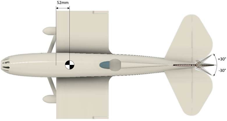
Figure 12: Center of gravity (CG) and rudder deflection angles
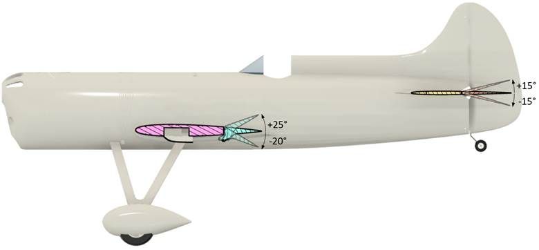
Figure 13: Aileron and elevator deflection angles
Change log
Version 3.1
· Added tubes to optionally stabilize the fuselage
with Ø 1.5mm carbon rods.
Version 3
· Optimized inner structures to improve compatibility of the STL files with freely available slicer versions such as Ultimaker Cura 5.3.1 or PrusaSlicer 2.7.1. It is possible to rescale and print this airplane with other nozzle diameters. Correct downscaling of the original 3D print size to 60% could be confirmed with Ultimaker Cura and PrusaSlicer. Upscaling should be only limited by the print volume of your printer.
|
Parameter |
Original 3D-print size |
Smaller |
Larger |
|
Nozzle Ø: |
0.4 mm (100%) |
0.3 mm (75%) |
0.5 mm (125%) |
|
Scale: |
1 : 6.5 |
1 : 8.13 |
1 : 4,88 |
|
Wingspan: |
1000 mm |
750 mm |
1250 mm |
|
Length: |
850 mm |
638 mm |
1063 mm |
· Moved from Ultimaker Cura to PrusaSlicer due to notably improved print quality of PrusaSlicer with my Prusa i3 MK3S. Latest slicer versions include a feature called "Arachne” which causes surface quality degradation for several parts of this model. Unfortunately, Ultimaker Cura does not allow it to switch off this feature completely. On the other hand, PrusaSlicer allows to deactivate this option which I’ve used for all print parts except for the canopy. In summary, I recommend using PrusaSlicer 2.7.1 (tested) or later together with the newly created project files and optimized print settings.
· Increased battery compartment to support batteries with a larger form factor.
· Optimized connection of wing parts. It now features an improved 3mm continuously overlapping outer perimeter to simplify alignment and gluing of the parts which also results in an improved surface finish.
· Added carbon tube support for the horizontal stabilizer in PLA.
· Modified rib structure of tail and aileron parts to improve rigidity and print quality.
· Improved tires by replacing internal structure with gyroid infill.
· Optimized print parameters with respect to print time and quality.
· Partly replaced continuous brim by selective brim to reduce assembly time.
· Merged landing gear crossbar halves. By default, the crossbar will be printed in PLA. Nonetheless, I recommend printing it with white TPU to improve stability and add some suspension in case of hard landings.
· Fixed a small issue with the wing servo covers.
· Changed filament recommendation for the wind shield from PETG to PLA. The Fillamentum PLA Crystal Clear Iceland Blue is easier to print and looks amazing.
· Added filament recommendation to use Overture Air instead of PLA+ to reduce the weight of the printed parts by ~20%.
Version 2.2
Minor modifications based on customer feedback.
· Increased engine side pull from 3 degrees to 4 degrees. This change improves take-off behavior.
· Slightly increased the wheel opening of the landing gear wheel pants.
Version 2.1
· Added carbon fiber pipe support for wing reinforcement to have an additional robustness margin for cutting flight maneuvers. Normal aerobatic figures with limited g-force such as a larger looping, turn or roll do not require such additional reinforcement.
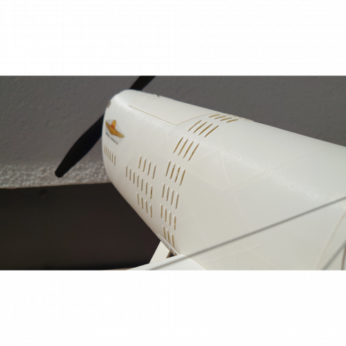
· Increased fuselage louver openings for improved scale impression – looks even greater!
· Reinforced landing gear wheel pants and crossbar.
· Reinforced internal structure of main wheels.
· Fuselage bottom seam part optimization for print quality improvement
Version 2.1 weighs 35g more compared to version 2 at the benefit of reinforced structures where needed. This additional weight has marginal impact on the center of gravity.
Version 2
· Support of active foaming LW-PLA printing for weight-critical components with a total print weight reduction of approx. 50g.
o Stabilizers, rudders, ailerons, and wing servo covers can be optionally printed with active foaming LW-PLA. Note that the weight reduction of the tail parts allows to additionally save motor and/or battery weight of up to 70g due to leverage with respect to center of gravity.
o The active foaming LW-PLA horizontal stabilizers and their connection to the fuselage feature tubes to optionally insert a 2mm carbon fiber rod. The rod is intended as an alternative for the tail flying wires.
o Provision of modified STL files, gcode for each part and Cura project files with all required active foaming LW-PLA print settings.
· Extension of the compartment for the battery (and the ESC).
o Provides more degrees of freedom in the choice of battery type and size, especially in combination with active foaming LW-PLA printed parts. Maximum supported dimensions are 140mm x 38mm x 28.5mm.
o Simplified the required cut out of the battery compartment.
· Weight reduction of the landing gear by approx. 13g.
o Mainly realized by reducing the diameter of the spring steel wires. The crossbar is now slightly thicker to ensure robustness.
· Improvement of all wing part connections resulting in increased stability and print quality.
o Added connectors to central wing parts to simplify the step of exactly aligning and gluing together both wing halves.
· Further optimization of general and part specific print parameters
· Several smaller improvements
Video
Shop Policies
Delivery Policy
Digital files for own printing will be made available for download (no shipping costs).
Printed parts:
To ensure proper delivery and happy customers, products will be shipped with DHL, which is part of the world's leading logistics company DHL Group.
Refund policy: 30 days return. Buyer pays return shipping.
Delivery is currently available in the following regions:
· Germany
· Great Britain and Switzerland
· All other EU countries
· Most other countries of Europe
The shipping costs depend on the delivery destination. For countries other than Germany, you may select between two options:
· Excluding insurance and tracking. No reimbursement from DHL or the seller if the package gets damaged or lost during delivery. -> less expensive
· Including insurance and tracking. Reimbursement from DHL if the package gets damaged or lost during delivery. -> more expensive
Contact: 3dprcfun@gmx.net
Refund Policy
30 days return for physical products (printed parts). Buyer pays return shipping.
Rating & Reviews
Based on 0 Ratings
- 5 Star
- 4 Star
- 3 Star
- 2 Star
- 1 Star